Skip to content
07944 877 329 hello@alectrona.solar

Alectrona

Commercial mounting

Mounting commercial solar on coastal and exposed sites

Near open water and on open ground the wind case and the corrosion case are both harder, so an exposed array is held down to a zoned wind calculation and specified from a corrosivity category rather than an inland default.

  • Survey-led, structure confirmed
  • Non-penetrative where possible
  • Over 50 kWp, outside MCS
Key facts
  • Wind actions Exposure terms assessed to BS EN 1991-1-4 and its UK National Annex for the actual site
  • Holding it down A zoned pattern, with heavier restraint at the corners and perimeter than in the field
  • Corrosivity Classified under ISO 9223, and the category sets the bill of materials
  • Materials A4 stainless fasteners, galvanising to BS EN ISO 1461, a stated anodising thickness
  • Scope Over 50 kWp, outside MCS; assured by standards, G99 and CDM 2015

A roof beside open water, on reclaimed levels or on an open frontage is a harder design case than the same roof four miles inland, and it is harder in two separate ways. The wind case is harder because there is nothing upwind to slow the air, so the uplift the mounting system has to hold down is greater and it is concentrated at the edges and corners. The corrosion case is harder because the air carries chloride, which works on fasteners, coatings and electrical connections across the twenty-five years the array is meant to last. Neither of those is answered by solving the other.

This page sets out what actually changes. How the exposure terms are established before a layout is drawn, why the ballast pattern is zoned rather than repeated from parapet to parapet, what the corrosivity category does to the bill of materials, and which details have to be drawn in the design package because they cannot be inspected once the array is complete. The figures are not published here, because the right ones are calculated for your building and its actual position rather than read off a table. The method is published, so you can hold a competing specification against it.

A commercial solar installation

Non-penetrative mounting where the roof allows.

Exposure is a term in the wind calculation, not a description of the view

Wind loading for a rooftop array is assessed to BS EN 1991-1-4 and its UK National Annex, and on a coastal or estuary site almost every term in that assessment moves the wrong way. The site is close to the sea, so the annex applies its least forgiving treatment. The upwind fetch across open water and reclaimed levels carries no roughness to slow the wind. There is no town terrain to shelter behind on a dock estate or an open industrial frontage. Low site altitude is usually the one term that helps.

The practical consequence is that two sheds of identical span and roof build-up, one on a dock estate and one on an estate ring road four miles inland, are not the same design case. Treating them as one is the commonest way an exposed array ends up under-fixed. The exposure terms are established for the actual site before a layout is drawn, rather than inferred from a postcode or from how sheltered the yard felt on the day of the survey.

Wind actions

The four terms that move on an exposed site

  • Distance to sea The National Annex applies its least forgiving treatment close to the coast so a coastal site starts from a harder design case than an inland one of the same span
  • Upwind fetch Open water and reclaimed levels carry no roughness to slow the wind terrain is read upwind of the building rather than around it
  • Town terrain There is nothing to shelter behind on a dock estate or an open frontage the sheltering allowance an urban site relies on does not apply
  • Site altitude Low ground is the one term that usually helps a coastal site and it rarely offsets the other three

Uplift is not uniform across a flat roof, so the ballast pattern must not be either

Uplift is not uniform across a flat roof. The corner and edge zones carry far higher suction than the field, so a ballasted system laid to one repeated pattern from parapet to parapet is the wrong answer on an exposed site. What we set instead is a zoned layout: a real setback from the roof edge, increased ballast or added mechanical fixing at the corners and perimeter, and frame geometry chosen for its wind behaviour rather than for the row count it allows.

Zoning costs roof area, and that is the honest trade. The setback and the heavier perimeter take modules out of the layout, so an exposed roof carries less capacity than its gross area suggests. Designing the zones first and counting the modules afterwards gives a system that stays where it was put. Counting the modules first and hoping the perimeter behaves is how an array is lost in a single winter.

Holding it down

Ballast, mechanical fixing, or both

The structure decides, not the preference, and the decision follows the structural survey rather than the quotation.

Ballast alone

Leaves the waterproofing intact, which is usually the reason to choose it. The cost is dead load, and on an older shed the frame may have no spare capacity to spend. On an exposed site the ballast requirement is highest exactly where the structure is often weakest, around the perimeter.

Mechanical fixing

Removes the dead load but adds penetrations, brings the roof warranty holder into the conversation, and requires fixings to land in purlins rather than sheet crowns. It is frequently the better structural answer where the frame has no margin to give.

Both, zoned

On genuinely exposed roofs the answer is often both, with mechanical restraint concentrated in the corner and perimeter zones and ballast carrying the field.

Cyclic uplift works fasteners loose over years rather than in one storm, so a torque check belongs in the maintenance schedule from the first year rather than the fifth.

Atmospheric corrosivity is a classified quantity, and it sets the bill of materials

Atmospheric corrosivity is classified under ISO 9223, running from the mild inland categories up through the marine and heavy-industrial ones. A roof beside an estuary or on an open coast sits a long way up that scale, and the consequence is blunt: an array specified to a perfectly reasonable inland standard is under-specified the moment it is craned onto the roof.

The modules are the least of it. It is the things holding them up and wiring them together that decide the twenty-five-year outcome, and each one is a line somebody can either specify properly or leave to whatever arrives on the lorry. The corrosivity assessment therefore belongs at the start of the design, because it changes the bill of materials rather than the layout, and a bill of materials is not something that can be corrected on the roof.

The materials schedule

What changes on a coastal specification

  • IEC 61701 Salt-mist corrosion testing for the modules specified at a severity matching the site, rather than the lowest level a datasheet can quote
  • A4 stainless Fasteners in place of A2 the molybdenum content is what resists chloride pitting
  • BS EN ISO 1461 Hot-dip galvanising on steelwork zinc is consumed faster in chloride-laden air, so the interval to first maintenance is shorter than the same coating gives inland
  • Stated anodising Coating thickness on mounting aluminium given as a figure an assumed thickness is the commonest silent substitution

Where two metals meet, the isolation detail is drawn rather than left to the day

Wherever dissimilar metals meet, the isolation detail has to be drawn rather than left to the installer on the day. A galvanic couple in salt air is a corrosion cell with a power source: the moisture film is conductive, the chloride keeps it conductive, and the less noble metal is consumed to protect the other one. Aluminium rail against stainless fixings, a steel purlin under an aluminium foot, a copper earth strap on an aluminium frame, each of those is a detail with a right answer and several wrong ones.

The right answers are ordinary engineering: an isolating washer or bushing, a compatible fastener grade, a sacrificial layer where separation is impractical, and a fixing schedule that says which is used where. What makes them worth drawing is that none of them can be inspected afterwards without taking the array apart. On an exposed site the isolation details belong in the design package, not in an installation method statement written the week before.

The DC connections are where coastal systems fail early

The electrical connections are where coastal systems most often fail early. DC connectors should come from one manufacturer and be crimped with that manufacturer's tool. Cross-mating two brands that both claim the same standard gives a joint that passes a visual inspection and then degrades quietly, which is the worst of both outcomes because nothing on site looks wrong.

An ingress rating is a laboratory result rather than a substitute for a correct crimp. A high-resistance joint in humid, chloride-bearing air heats, and in a DC circuit that is how roof fires start. The same reasoning puts inverters inside the building wherever the design allows, and on its sheltered face where it does not, because an enclosure rated for the weather is still an enclosure breathing salt air twice a day. String terminations, earthing points and the isolation between dissimilar metals are then inspected as corrosion items rather than only as output items.

Reading the site

Exposed and corrosive are two separate axes

Both are assessed for every site, and they do not travel together.

Exposed and corrosive

An estuary or open-coast frontage, with no upwind roughness, the highest corrosivity on the scale and often an older structure underneath. Zoned ballast, real edge setbacks and a full marine specification.

Exposed, but not corrosive

Flat, low-lying agricultural levels well inland of open sea. Brackish or negligible salt influence, so the corrosivity assessment usually lands a category or more lower, while the wind case stays as hard as the coast because there is still nothing upwind.

Neither

A site several miles inland with rising ground behind it. Standard anodising, conventional stainless grades, an ordinary ballast calculation, and inverters that can sit wherever the electrical design prefers. This is the control case that shows what the coastal premium actually consists of.

Assuming the two axes travel together is how an array on open inland levels ends up with the ballast pattern of a sheltered urban valley.

The survey reads the corrosion the roof has already suffered

On an exposed site the survey does more work than usual, because the specification depends on things a satellite image cannot show: parapet heights and the setbacks they allow, the exact position of condensers and plant, the cladding profile and its fixing type, and the corrosion already visible on flashings, gutters, fixings and rooftop steelwork.

That last item is the most useful single piece of evidence available. A roof that has stood in this air for twenty years has already run the test we would otherwise be predicting, and what has happened to its fixings, its flashings and its gutter joints is a direct read on what will happen to an array bolted to it. Wind also narrows the flying window on an exposed roof, so the visit is planned around the forecast rather than the diary, and on a live process building the access is agreed with whoever runs the plant before the date is set. The structural side of the same visit is covered in our guide to the structural roof survey.

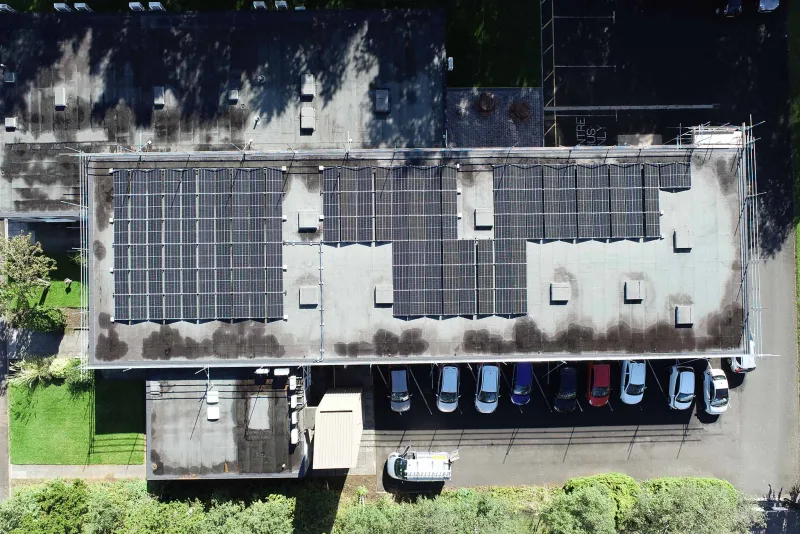
Indicative layout · a scaled 3D model from a real drone survey, not a satellite estimate.

Inland and sheltered are two different things. The wind case and the corrosion case are answered separately. On this kind of roof, the specification is the design.

The battery cabinet carries a corrosion grade as well as the array

Corrosivity does not stop at the roofline. Anything standing in the same air meets the same chloride, and on most commercial sites the largest thing outdoors after the array is the battery cabinet. Storage manufacturers grade the enclosure for it. The Solis EverCore and PrimePower cabinets are offered in a standard build and in a C5 version, and that C5 is the same ISO 9223 corrosivity class the fastener and coating schedule on this page is written from. Choosing the cabinet grade is the same decision as choosing A4 stainless over A2, taken about a different part of the system.

So on an exposed site the storage question carries a site condition alongside the power and the energy the cabinet has to deliver. Where it stands, whether it can sit on the sheltered face of the building, how the plinth and the cable entries are detailed, and which enclosure version is ordered belong in the same specification as the mounting, settled at survey rather than left to whichever build is quickest to source. Our Solis page sets out how those cabinet versions differ, and commercial battery storage covers how a cabinet is sized and sited before any of that is chosen.

Maintenance on an exposed site is a performance measure

What a maintenance plan contains changes with the exposure. Near open water it includes fastener torque checks against cyclic uplift, inspection of connectors and earthing points for corrosion rather than only for output, and a scheduled clean, because salt deposition and gull fouling build soiling faster than an inland site ever will. Several miles inland the same array needs less, and saying so is part of the specification rather than a discount.

Torque is the item most often left out. Cyclic uplift works fasteners loose over years rather than in one storm, so the first torque check belongs in year one and at a stated interval after it, with the values recorded. An array that is never re-torqued on an exposed roof is an array whose fixing schedule slowly stops being true. Our guide to commercial solar maintenance sets out the baseline plan that this exposure schedule is added to.

Three rules for a roof in this air

Three rules govern how we work on an exposed site, and each is meant to be checkable rather than reassuring.

Specify from the site, not the postcode. The exposure terms and the corrosivity category are established for the building's actual position, upwind fetch included, before a bill of materials is written. A distance from the coast is not a specification, and neither is an impression that the yard felt sheltered on the day.

Draw what cannot be inspected later. Galvanic isolation, connector crimping and the fixing and torque schedule are settled in the design package, because none of them can be checked once the array is complete without taking it apart. A detail left to a method statement written the week before is a detail nobody will verify.

Read the corrosion already there. Twenty years of flashings, gutters and fixings on that building is a better predictor of the next twenty-five than any calculation made from a map, so the survey records what has already happened to the roof before anything is specified for it.

FAQ

Coastal and exposed sites: common questions

Yes, and in two separate respects. The wind case is harder, so the ballast or fixing pattern is zoned, with heavier restraint at the roof edges and corners than in the field. The corrosion case is harder, so fasteners, coatings and connectors are specified to a marine standard rather than an inland default. Both are established for your building before a layout is drawn, from the exposure terms in BS EN 1991-1-4 and the atmospheric corrosivity category under ISO 9223.

From the site itself. Wind actions are assessed to BS EN 1991-1-4 and its UK National Annex, and the terms that matter most near open water are the distance to the sea, the upwind fetch, whether there is town terrain to shelter behind, and the site altitude. On a dock estate or an open frontage the first three all move against the design and low ground rarely offsets them. We establish those terms for the actual building rather than infer them from a postcode, and because the resulting figure belongs to your roof we do not publish one here.

ISO 9223 classifies atmospheric corrosivity, from the mild inland categories up through the marine and heavy-industrial ones. A roof beside an estuary or on an open coast sits a long way up that scale, and the category is what sets the bill of materials rather than the layout. An array specified to a perfectly reasonable inland standard is under-specified the moment it reaches that roof, and a bill of materials cannot be corrected afterwards without taking the array apart.

Near open water, usually. In practice that means A4 stainless fasteners in place of A2, because the molybdenum content is what resists chloride pitting, hot-dip galvanising to BS EN ISO 1461 on steelwork, a stated anodising thickness on the mounting aluminium rather than an assumed one, and modules salt-mist tested to IEC 61701 at a severity matching the site rather than the lowest level a datasheet can quote. Which of those your site needs follows from the corrosivity assessment, not from a rule of thumb.

Not automatically. Module and mounting warranties commonly reduce or exclude cover within a stated distance of salt water unless a marine variant is specified, and both the distance and the wording differ by manufacturer. We read the warranty terms for the products proposed for your site against the site's own position before anything is ordered, and where a marine variant is required we specify it rather than accept a standard product with a shortened warranty quietly attached to it.

No. Exposure and corrosivity are two separate axes and they do not travel together. Flat, low-lying agricultural levels well inland of open sea can carry a wind case as hard as the coast, because there is still nothing upwind, while the corrosivity assessment usually lands a category or more lower. Assuming the two go together is how an array on open inland ground ends up with the ballast pattern of a sheltered urban valley.

Get a commercial quote

Get a commercial mounting assessment

Tell us about the roof or the site. We survey it, confirm the structure, then specify the mounting system that fits, with no penetrations where the roof allows.

  • On-site 3D drone survey and structural check
  • Non-penetrative where the roof allows
  • Over 50 kWp, outside MCS