Skip to content

Alectrona

Commercial mounting

Ground-mount solar for commercial sites

When you have spare land, a yard or a field instead of usable roof, a ground-mount array puts the system where the sun is, with open access for installation and maintenance. The frame type is decided by the ground itself, so a geotechnical survey and a PV*SOL model come before any layout is fixed.

  • Survey-led, structure confirmed
  • Non-penetrative where possible
  • Over 50 kWp, outside MCS
Reviews

The feedback we work to earn

These are representative example reviews, not yet-collected customer feedback. They are written to illustrate the kind of feedback Alectrona aims to earn and are shown as design placeholders while we gather and verify reviews from our first commercial clients. Alectrona is the commercial solar trading brand of RVTC LTD.

What set Alectrona apart was the documented design pack. We had quotes from three installers, but only Alectrona handed us a full set of drawings, a single-line diagram and a design referencing BS 7671 and the G99 connection process. The whole thing read like an engineering submission rather than a sales brochure. Our M&E consultant reviewed it and signed it off without a single query. That gave the board the confidence to release the capital.

Estates Manager, academy trust (Yorkshire)

Other firms priced our roof off a satellite image and a desktop guess. Alectrona flew an in-house drone survey, fully insured and flown by a qualified commercial drone pilot, and built a 3D model of the actual roof. It picked up plant, vents and a parapet line that a flat aerial photo had completely missed, which changed the panel layout. I would rather find that out at design stage than on the day the scaffold goes up. The accuracy of that survey is the reason I trusted everything that followed.

Facilities Manager, distribution centre (East Midlands)

As a finance director I was wary of being oversold a system bigger than we could use. Alectrona modelled the array against our actual half-hourly consumption data rather than an annual total, so it is sized to what we genuinely draw on site during the day. They were honest that exporting surplus is worth far less than self-consumption, and built the design around that. The capital case stacked up because the engineering was honest, not because the numbers were inflated.

Finance Director, logistics group (North West)

We were undecided between buying outright, leasing and a PPA. Alectrona laid out all three side by side with the pros and cons of each against our balance sheet, instead of pushing the one that pays them best. They were clear about where a PPA makes sense and where capex wins, and pointed us at our own accountant for the tax treatment. The survey and design took a little longer than I expected, but the thoroughness was worth the wait. Genuinely consultative.

Property Director, retail park (West Midlands)

The install crew were tidy and well run, and worked to a clear CDM 2015 plan with a proper site induction and RAMS. What impressed me most was the handover. We received a full commissioning pack with the IEC 62446-1 test results, certification, O&M documentation and an as-built record for our maintenance team. As the people who have to live with this asset for the next twenty years, having that paperwork in order matters enormously. Nothing was left loose.

Operations Director, food manufacturer (Lincolnshire)

I expected the usual hard sell and got the opposite. After surveying our site Alectrona told us one roof section was not worth covering because of shading, and that a smaller, well-sited array was the better investment than filling every square metre. There was no commission-driven upselling and no pressure. For a six-figure capital project, that straight talk is exactly what you want from the people advising you. We will be using them again on our second site.

Managing Director, engineering firm (Sheffield)

Key facts
  • Penetrative foundations Driven or screw piles into the ground; sized from a site pile test
  • Ballasted frames Non-penetrative, weight-held where the ground must not be pierced
  • Foundation choice Decided by the geotechnical survey rather than a catalogue
  • Bifacial gain Rear-side yield depends on surface albedo; modelled rather than assumed
  • Planning and scale Most non-trivial ground arrays need full planning consent

A ground-mount array is a steel or aluminium frame that holds the panels in fixed rows across open land rather than on a building. It suits commercial sites with land to spare: a haulage yard, a former lagoon, set-aside ground next to a unit, or a field a landowner wants to put to work. Because the array is not tied to a roof, the row pitch, tilt and orientation can be set for yield rather than for whatever the building happens to offer, and maintenance access is at ground level.

The engineering question that decides everything else is how the frame is anchored, and that is a ground question rather than a catalogue choice. The two broad routes are penetrative foundations, where posts are driven or screwed into the ground, and non-penetrative ballast, where the frame is held down by weight on the surface. Which one a site needs is determined by the soil, the water table and the wind loading, confirmed by the geotechnical survey for your ground. This page sets out the principles so you know what shapes the design before we model it.

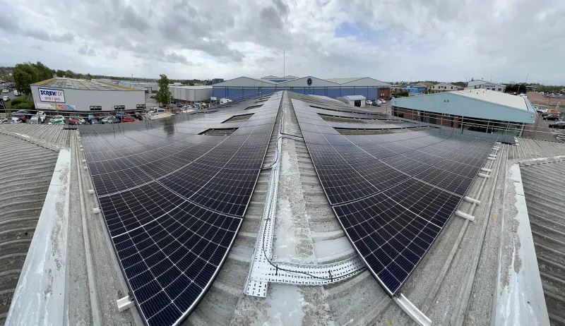
A commercial solar installation

The fixing follows the roof, confirmed by the structural survey.

Driven-pile and screw-pile foundations

On most ground with reasonable bearing capacity, the frame is anchored by foundations that penetrate the soil. Driven piles are steel posts hammered directly into the ground to a depth the engineering calls for. Screw piles, sometimes called ground screws, are threaded posts wound into the soil like a large screw. Both transfer the array's wind and weight loads into the ground without concrete in the common case, which keeps the groundworks light and the install quick, and both can be removed at end of life so the land returns to its prior state.

The right depth, post spacing and pile type are an engineering output rather than a fixed number, because they depend on the soil's bearing capacity, the wind zone and the array's exposure. A trial pile or pull-out test on site gives the real holding capacity of your ground, and the foundation design is confirmed from that test and the geotechnical survey rather than assumed from a standard table.

Ballasted frames where the ground cannot be penetrated

Some sites rule out driven or screwed foundations: a capped landfill or contaminated ground where the membrane must not be pierced, a hardstanding slab, made ground full of obstructions, or a site where penetration is not permitted. There the array sits on a non-penetrative ballasted frame, held in place by weight on the surface, typically concrete blocks or ballast trays, with no anchor breaking the ground.

Ballast is a deliberate engineering trade. The frame stays on the surface, but it must carry enough mass to resist wind uplift and sliding across the whole array, and the ground beneath has to bear that distributed load. The ballast mass needed for your site is calculated against the wind loading and the surface it sits on, confirmed by the structural calculation and the geotechnical survey, not taken from a generic figure.

Row layout, tilt and shading

On open land the array geometry is set for performance rather than dictated by a roof. Rows are pitched and spaced so that, through the working day and across the year, one row does not throw shade onto the row behind it more than the design allows. A wider row gap lifts winter yield and cuts inter-row shading but uses more land, so the layout balances energy against the area available. Orientation is usually toward the south for output, though an east-west layout can pack more capacity onto a tight plot.

The tilt angle, row pitch and any tracking are chosen against your latitude, the land area and the shape of the plot, then modelled in PV*SOL so the predicted yield reflects the real geometry and the real horizon. Nearby trees, buildings and the site's own slope are built into that model rather than ignored, because the shading on your ground is specific to your ground.

Panel choice and bifacial gain on the ground

Ground-mount is where bifacial modules can earn their place. A bifacial panel generates from its rear face as well as its front, picking up light reflected off the surface beneath and behind the array. On the ground that rear-side gain depends on the surface albedo: pale gravel, concrete or grass reflects more than dark earth or tarmac, and a higher frame that sees more reflected light gains more than a low one. The gain is real but site-specific, so it is modelled for your surface and array height in PV*SOL rather than assumed from a headline percentage.

Cell technology is chosen on the same evidence basis. TOPCon, heterojunction and PERC are different cell architectures with different trade-offs in efficiency, behaviour in heat and cost per watt, and none of them is universally best across every site. On a ground array where land is plentiful, a bankable value module on a wider layout can beat a premium module on a tighter one, so we name the specific module, its scheme and its grade for your project and re-verify the credential before contract.

Planning, grid and how the design is signed off

Ground-mount carries obligations a rooftop array does not. Permitted development rights for stand-alone ground arrays on commercial land are far more limited, so most schemes beyond a modest size need a full planning application that weighs landscape, ecology, drainage and access, and that adds lead time to the programme. The grid connection is sized to the array's export and applied for with the network operator early, because the connection terms can shape the viable capacity.

Because a commercial ground array sits above 50 kWp and outside the MCS scheme, the assurance comes from engineering rigour, named component standards and compliance with the CDM 2015 construction duties rather than a domestic certificate. We run the geotechnical survey, the structural calculation, the planning route check and the PV*SOL model as one survey-led process, so the layout you sign off is one that can be founded, consented and built on your land. Installs are contracted by RVTC LTD.

What wind and snow loading does to a ground array, and the codes that govern it

An open-field array is fully exposed, with no building to shelter it, so the dominant force on the structure is wind. Wind acts on the panel plane as both pressure and uplift, and because the rows stand proud of the ground the load tries to lift the front edge, push the array sideways and overturn it about the rear foundation. The frame, the foundations and the panel clamps all have to carry that load path into the ground. Snow adds a downward case that bears on the modules and the rails, and on a tilted array it can drift and slide, loading the lower edge unevenly.

The loads themselves are not a single catalogue number. They are derived from the wind code and the snow code for your specific location, exposure and array height, which in UK practice means the structural Eurocodes for wind action and snow load applied with the national parameters for your site, then carried through the frame design and the foundation design. The fixed electrical installation is built and tested to BS 7671, while the structure answers to structural standards and the CDM 2015 duties rather than a domestic certificate. We do not quote a load figure on a web page, because the right figure is calculated for your ground and your wind zone rather than read off a standard table. That structural calculation, alongside the geotechnical survey, is what fixes the post spacing, the pile depth and the ballast mass before any row is set out.

What the ground survey actually looks for before a layout is fixed

The geotechnical survey is the piece of work that decides whether the array can be founded at all, and how. Trial pits or boreholes across the plot establish the soil profile, its bearing capacity and how it changes from one corner to another, because made ground, a former lagoon or a yard that has been built up over decades rarely behaves the same across the whole footprint. The survey also reads the water table, which governs whether a driven pile holds or works loose, and the depth of any soft, peaty or contaminated layers that a foundation must reach through or avoid piercing.

Three further findings shape the design directly. Frost penetration depth sets how deep a foundation must sit so a winter freeze does not heave it. Ground aggressivity, the soil chemistry and resistivity, governs how a buried steel post will corrode and therefore what protection or section it needs to last the design life. And buried services, drains and any membrane on a capped site dictate where foundations cannot go. A trial pile and an on-site pull-out test then give the real holding capacity of your ground rather than an assumed one, which is why the foundation route is confirmed from the survey and the on-site test for your plot rather than from a generic specification. The same survey feeds the cost picture, because groundworks are where a ground-mount budget is genuinely won or lost.

Indicative layout · a scaled 3D model from a real drone survey, not a satellite estimate.

The failure modes a ground-mount design is built to prevent

Most ground-mount problems trace back to the ground or the loading being misjudged, and naming the failure modes is the clearest way to see why the survey work matters. Wind uplift pulling a row free is the headline risk on an exposed plot, so the foundation and the ballast calculation are driven by uplift as much as by the array's downward weight. Frost heave can lift a shallow foundation over successive winters until the rows go out of alignment. Differential settlement, where one part of the array sinks faster than another across variable ground, racks the frame and stresses the module clamps. On sloping or poorly drained land, surface water scour can wash material away from a foundation and undermine it.

Two slower failure modes also sit in the design life. Buried steel corrodes at a rate set by the soil chemistry the survey measured, so the wrong section or the wrong protection shortens the life of the foundation. And ground movement on made or reclaimed land, including ongoing settlement of a former tip, keeps acting on the structure long after commissioning. A ballasted frame answers a different subset of these, because it cannot heave or corrode below ground, but it must instead carry enough mass to resist sliding and overturning across the whole array. Designing against the right failure modes for your ground is precisely what the structural calculation and the geotechnical survey exist to do, which is the same engineer-led process we run for every commercial system.

Cabling, earthing and protecting an array nobody is standing under

A ground array changes the electrical job as much as the structural one. The DC string cabling runs across open land between rows and back to the inverters, so it is routed in cable trays or buried ducts, protected against rodents, UV and mechanical damage, and kept to string lengths that hold the voltage drop within limits. Long DC runs across a field are a real design constraint, and where the geometry pushes them too far the inverter positions or the string design are revised so the losses stay within limits.

Earthing and bonding carry extra weight on the ground. The frame, the foundations and the array are bonded and earthed to BS 7671 so a fault cannot leave exposed metalwork live in a space people and machinery move through at ground level, and an exposed open site usually warrants lightning and surge protection that a sheltered roof might not. Because the array sits at head height and within reach rather than high on a roof, isolation, labelling, fencing and DC protection are designed so the system is safe to be near and safe to work on. All of this is part of the survey-led design and is contracted and installed by RVTC LTD, the trading name behind Alectrona, with the whole installation tested and certified before it is energised.

FAQ

Ground-mount: common questions

The ground does. Where the soil has reasonable bearing capacity and penetration is allowed, driven or screw piles are usually the lighter, quicker route. Where the ground must not be pierced, such as a capped landfill, a slab or made ground, the array sits on a non-penetrative ballasted frame held down by weight. A geotechnical survey and, for piles, an on-site pull-out test confirm which route your ground supports before any layout is fixed.
No, it is a different engineering route for a different ground condition. A ballasted frame resists wind uplift and sliding through the mass it carries rather than through an anchor in the soil, and the required ballast is calculated against the wind loading and the surface it sits on. It is the correct method where penetration is ruled out. The structural calculation for your site confirms the ballast needed; it is not taken from a generic figure.
Often, but it depends on the surface. A bifacial module generates from its rear face using light reflected off the ground behind and beneath the array, so a pale, reflective surface and a higher frame add more than dark earth or tarmac. The gain is real but specific to your site, so we model it in PV*SOL for your surface and array height rather than assume a headline percentage, and specify bifacial only where the model shows it pays.
None of them is universally best; they are cell architectures with different trade-offs in efficiency, performance in heat and cost. On open land where space is less constrained, a bankable value module on a wider layout can outperform a premium one on a tighter plot. We choose against your land area, geometry and the PV*SOL model, then name the specific module, its scheme and its grade for your project and re-verify the credential before contract.
Usually, yes. Permitted development rights for stand-alone ground arrays on commercial land are far more limited than for rooftop, and most schemes beyond a modest size need a full planning application covering landscape, ecology, drainage and access. That adds lead time, so we check the route early and build it into the programme. This is orientation, not formal planning advice, and we confirm the position for your specific site.
MCS is a domestic-scale certification that caps at 50 kWp, so it does not reach a commercial ground array. On work this size the engineering is the trust signal: a geotechnical survey, a structural foundation calculation, named component standards and compliance with the CDM 2015 construction duties. You sign off a layout backed by a site survey and a PV*SOL model rather than a domestic certificate, and the install is contracted by RVTC LTD.
Longer than a rooftop system, mainly because of planning and groundworks rather than the install itself. Most stand-alone ground arrays beyond a modest size need a full planning application, and that determination period, together with the geotechnical survey, the on-site pile test and the Northern Powergrid connection agreement, sets the real timeline more than the frame build does. We cannot put an honest week count on a web page, because the programme depends on the planning route, the ground conditions and the connection terms for your specific site. We map the critical path of planning, survey, DNO and procurement at survey stage and build it into a programme you can plan around.
Get a commercial quote

Get a commercial mounting assessment

Tell us about the roof or the site. We survey it, confirm the structure, then specify the mounting system that fits, with no penetrations where the roof allows.

  • On-site 3D drone survey and structural check
  • Non-penetrative where the roof allows
  • Over 50 kWp, outside MCS